Photointerruptor Test Circuit
28 Dec 2010
28 Dec 2010
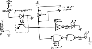
I made a circuit to test phototransistors I will be using for the encoder. I’m using these phototransistors. Here’s the schematic.

I am comparing the signal passing through a Schmitt trigger to one passing through a simple buffer made out of two NAND gates and testing what resistances are necessary for consistent sensing.

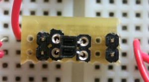
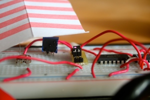
I made a small breakout board because the photosensor was too small to fit into the breadboard.

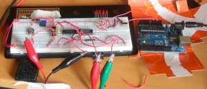
As Expected, the Schmitt trigger improves the signal transition enough relative to the simple buffer that it is even noticeable on the LEDs.

A photointerruptor can exist in several forms, but the one I used consists of an infrared LED and phototransistor pointing the same direction in a single package. When an object is placed in front of the photointerruptor, light from the LED is reflected back into the phototransistor and current can flow through it.

By placing a resistor in series with the LED, you can control the amount of current that flows through it. Since I want 30 mA, and from the spec sheet, I know that the forward voltage (across the led) is approx. 2.3v at 30mA, the resistor I need is:
From Ohm’s Law:
\[V=I\cdot R\]The voltage across the resistor (V) is 2.7V because the power source is 5V and the voltage across the resistor plus the voltage across the LED must add up to 5V. The current we are aiming for (I) is 30mA. Substituting for V and I and solving for R.
\[R = \frac{V}{I} = \frac{2.7 V}{30 mA} = 90 \Omega\]The amount of light the phototransistor receives determines the amount of current which can pass through it. The amount of current passing through the transistor varies little across different voltages relative to the resistor. Therefore, by measuring the voltage across the resistor we can determine how much current it is letting through and therefore whether it is receiving reflected light from the LED.
By inserting a buffer between the LED and the resistor, we can make it turn on and off depending on whether there is something present to reflect the light from the LED to the phototransistor. However, if we use a simple buffer, the output will not be crisp when it changes from high to low. It’s important to have crisp edges to our signal when we need to use it for something like an encoder. Therefore, we can use a Schmitt trigger instead of the simple buffer t0 filter the signal.